Mission Context
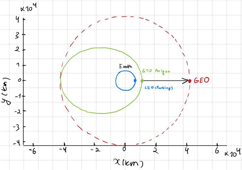
NASA’s Tracking and Data Relay Satellite System (TDRS) provides continuous communication links between LEO spacecraft — including the International Space Station and Hubble Space Telescope — and ground networks. Reaching the geostationary belt at 35,786 km altitude from a 300 km parking orbit demands a carefully sequenced multi-burn ascent that consumes the overwhelming majority of a spacecraft’s propellant. This project simulated the complete orbital trajectory and maneuver sequence for a TDRS-M-class spacecraft, analyzed the full Δv and mass budget, and designed a longitudinal phasing correction at GEO.
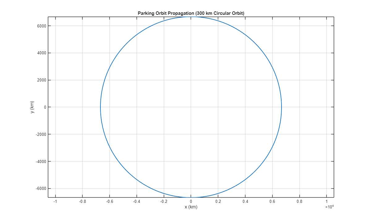
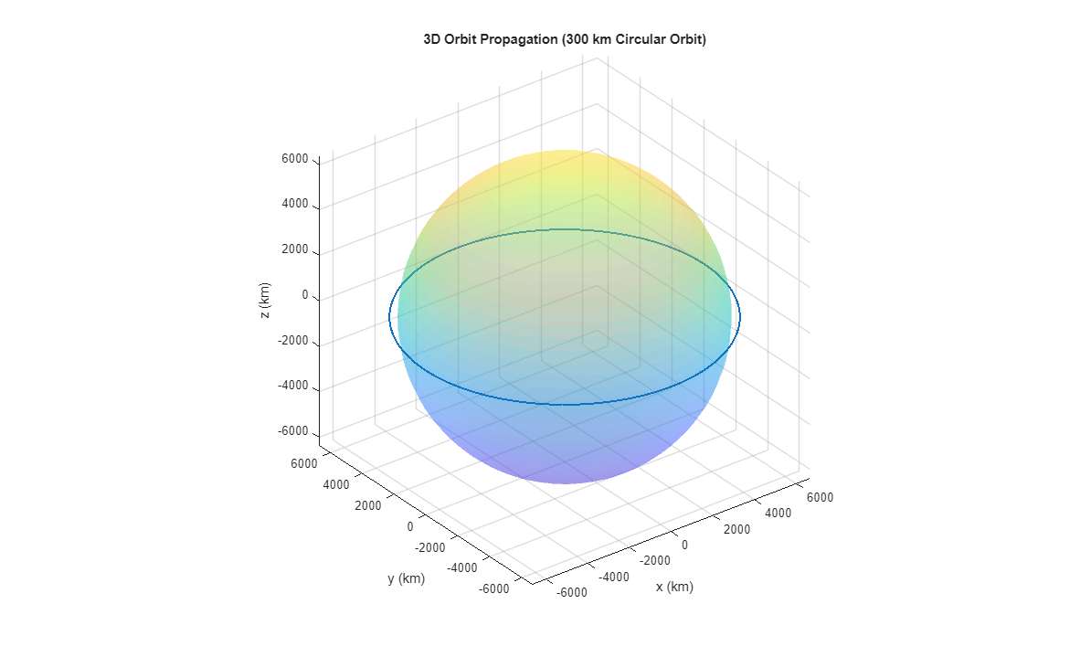
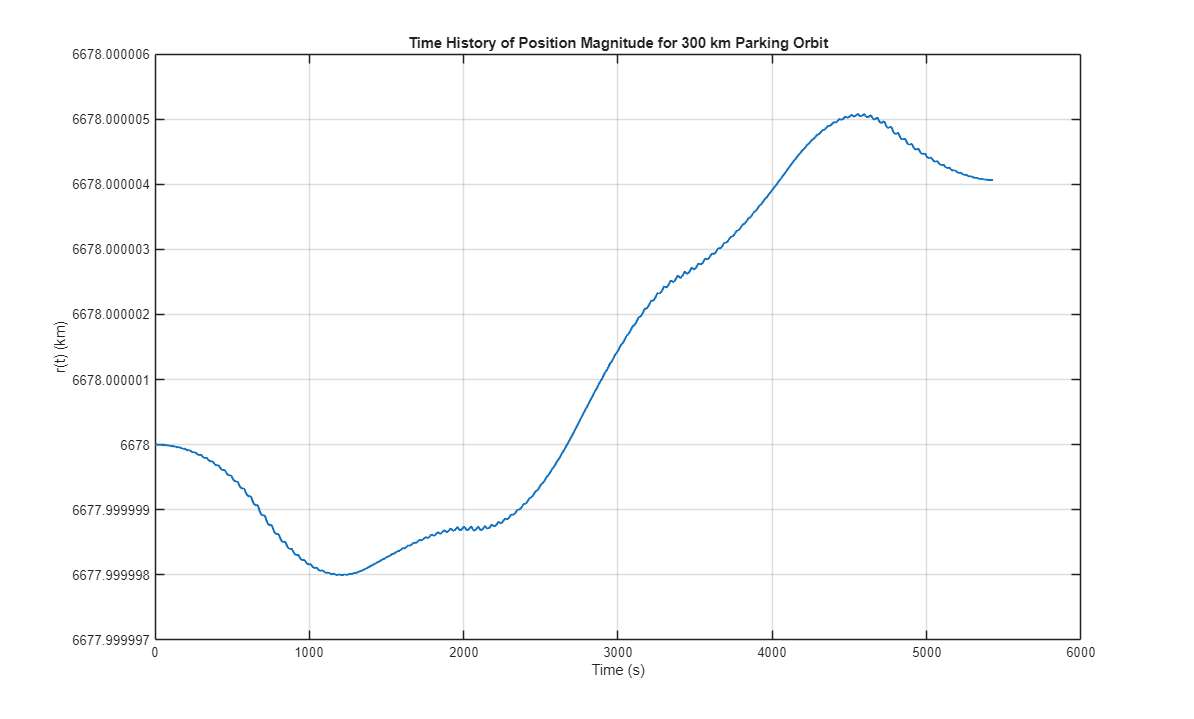
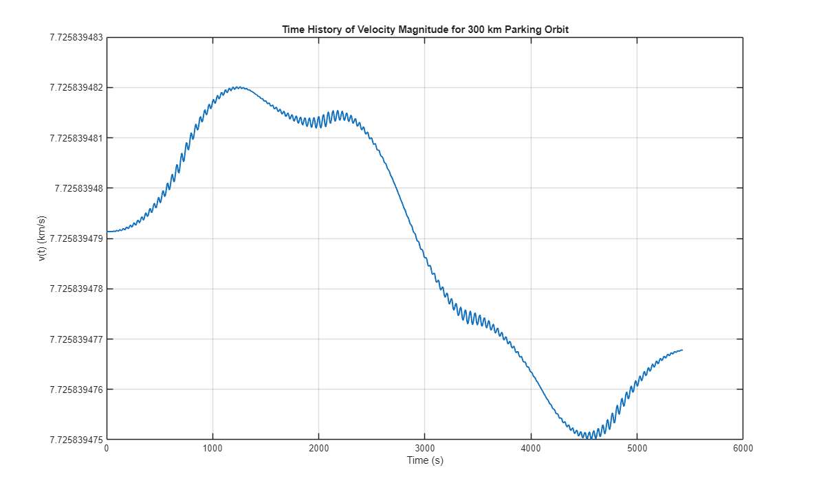
- Propagate a 300 km circular parking orbit via two-body equations of motion integrated with
ode45 - Compute Δv for the full LEO → GTO → GEO sequence, including a 28.5° plane change at apogee
- Estimate propellant mass and mass fraction using the Tsiolkovsky Rocket Equation (Isp = 320 s)
- Extract Classical Orbital Elements (COEs) at every major mission stage
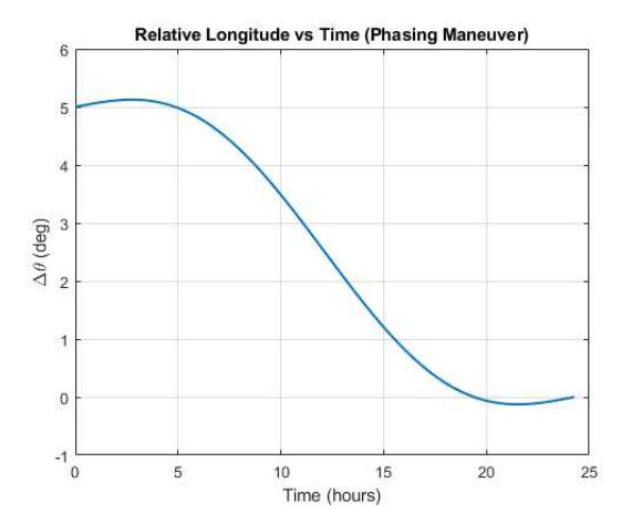
- Design and numerically validate a phasing maneuver correcting a 5° longitude offset between two GEO spacecraft
- Benchmark all simulation results against real TDRS-M (2017) mission data